How to Install RCRun RUN80 Steering Wheel

How to Install RCRun RUN80 Steering Wheel

May 31, 2023 – video comment from Oliver Walther

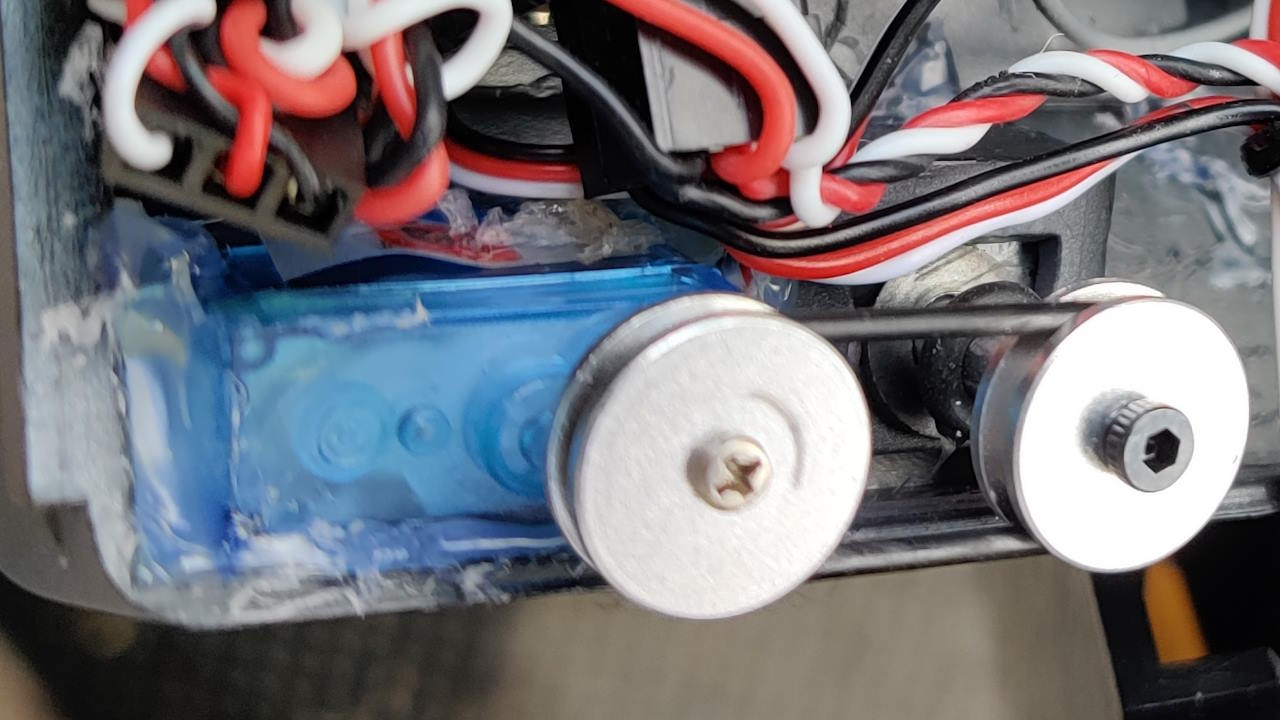
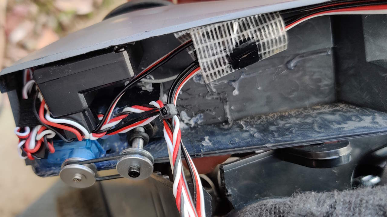
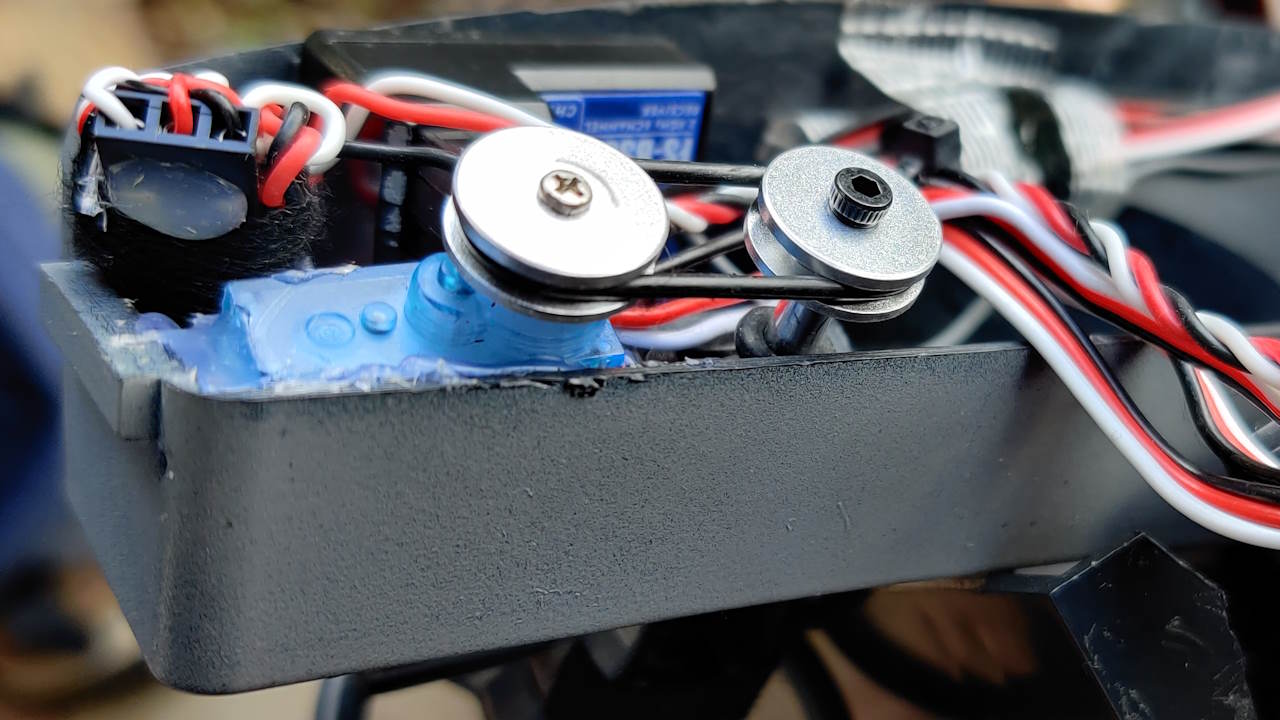
Could you give some information how to install the RCRun RUN80 steering wheel servo? I’ve got my kit and for the steering module there are only two alloy pullies and the micro servo. No frame for the servo or other stuff. I hope you could help. Ty from the other end of the rc world (germany) 😉


A. The RCRUN Run80 Landcruiser 80-Series body interior (available here) includes a steering assembly that steers with the steering servo input. (You can see a gif of this below). There’s a micro servo that is used to achieve this and it operates via a 1:1 pulley system inside the dash. The micro servo sits inside the plastic mold shape, but there’s no obvious retention mechanism for it.

You need to affix the servo to the bottom corner of the dash mold, and then align the two pulley wheels so the servo can turn the steering column. The whole mechanism is kinda weak and there is slop in the system, but it does work. It doesn’t have to work very hard, thankfully. (And if I was going through all this again, I probably would not worry about having the moving steering wheel – it just adds complexity and noise and you can barely see it when the car is driving – though it is definitely cool, which I totally do get).

Anyway, see below for a couple of photos I took of mine. I secured the servo with a bit of hot glue but you could use double-sided tape or some other glue and it should be fine. Hope that helps make it a bit clearer! We’ve got more general info about this amazing vehicle on our write-up, right here on the site.

-Craig

Steering Wheel Servo
RCRun RUN80 Steering
TRX4 Shocks on Vanquish Phoenix Portal VS4-10?

TRX4 Shocks on Vanquish Phoenix Portal VS4-10?

Oct 3, 2022 – video comment from John Barnicoat

I tried the TRX-4 shock substitution but found the adjustable shock/spring collar interferes with the Phoenix Portal’s shock mount area at the top. The collar is bigger in diameter than the stock shock, so it doesn’t fit all the way into the recess under the mount. How did you get these to fit?

A. Mine didn’t fit either. I had to dial the pre-load down a little so they’d fit. I wanted some pre-load anyway, so it wasn’t a problem. Some shock designs let you run without the collar at all, but these shocks don’t allow that. The difference between some and no pre-load is minimal at the front, but the rear is not quite the case.


I suppose you could cut away some of the shock mount around where the collar needs to go, but that wouldn’t be ideal for strength. You could put a softer spring in, or you could try a different shock of the same length. I don’t have a perfect answer in this case because we’re fitting two parts together that aren’t designed for that – but my testing on my rocks at least has shown this to be a good change. Tinker, test, then tinker some more – that’s all I can really suggest for this one! Hopefully you find a setting you like.

-Craig

Vanquish Phoenix Portal
Phoenix Portal Front-Left
Rear-Right Shock
Rear-Left Shock
Front-Right Shock

Smaller Tires on EX86110?

August 17, 2022 – video comment from Guly 15

RGT Pioneer EX86190: Is it possible to mount smaller rims and tires on the Pioneer? I’m thinking of maybe a similar dimension to the ones on the BRX01.

RGT Pioneer & Smaller Tires

A. The EX86110 can fit smaller tires – it’s a fairly standard hex and 5mm axle arrangement, typical of most 1/10 RC crawlers.

Be aware that not all wheels fit all trucks. Some have larger offsets that need wider axles, for example. Other wheels have thicker rims that can rub on steering knuckles or portal outer covers and/or weights.

For the EX86110 and smaller tires, your main concern will be rim thickness, as those axles are not particularly long. For the Team Raffee Steelie Beadlocks we photographed here for you, the wheel nut was only just able to bite onto the axle over the wheels, so thread lock would be advisable for these!

The first photo compares the smaller tires to the OEM EX86110 set. The second photo is them next to our red BRX01. The last two are with them mounted. Here’s what the wheels and tires are, and where to get them:

  • Team Raffee Co. 1.9 Steelie Beadlock Wheels (AsiaTees)
  • Team Raffee Co. 1.9 Crawler Tire 1.2″ Type B (AsiaTees)
Craig Veness

Craig Veness

RC-TNT

Craig has been into radio control since the 90s and into RC crawling since about 2010, when a Losi MRC started the obsession! Now it's all rocks this and crawl that and upgrade all the things! ...You know how it is, right? Welcome home 🙂

I Was Wrong! (Sorry, RGT!)

I Was Wrong! (Sorry, RGT!)

June 18, 2022 – video comment from El Duderino Lebowski

RGT Rescuer EX86190: I tried to find anywhere that described exactly which type of powder metal process was used to make the gears in this drivetrain, and I just couldn’t find anything. Is that because it’s proprietary industrial secrets for how good they are, or because they don’t want us to know how cheaply made they are? Lots of questions, no answers.

It would be interesting to find out more about these gears and how they were made. The way it’s worded does make it sound like a positive feature, which implies they’re made with one of the better methods, but at this price point, we can’t just accept that assumption.

There are a number of modern powdered metal processes that are actually superior to other forms of manufacturing and are preferred in high-stress high-performance and/or mission critical applications (HIP comes to mind here), so without knowing which method was used, it’s hard to gauge whether or not these are any good.

If these gears are [made well], no problem. …If these are just a cheap cast powder process (I really hope that’s not the case!), then yeah, your observations are spot on, and possibly somewhat optimistic, about their durability.

RGT Rescuer EX86190 Gears

A. Thanks for bringing this up, I should have done this in my review. Sorry I missed it!

I’ve taken the truck apart to see what we’re dealing with here. I found the transmission, diff and portal gears all have the same appearance. They’re smooth, not rough like the powder-coated cast gears I’ve seen from other manufacturers (eg. the BOM TC). They looked pretty good.

They were not magnetic, for whatever that’s worth. I’m not familiar with latest manufacturing methods but given the smooth surfaces even on the gear teeth, I’m inclined to think this process must be alright. Certainly, the gears have stood up to considerable use already in my unit. I’ve used it in all weather, including under water and in mud, with no maintenance until today. 

Service Time!

I dried everything out, applied a fresh glob of moly grease to everything, and bolted it all back together. If anything changes on this front, I’ll update this post and let you all know in a Community post. So far, so good! -Craig

Craig Veness

Craig Veness

RC-TNT

Craig has been into radio control since the 90s and into RC crawling since about 2010, when a Losi MRC started the obsession! Now it's all rocks this and crawl that and upgrade all the things! ...You know how it is, right? Welcome home 🙂

Does the TRX4 Sport Fit the DC1 Body?

Does the TRX4 Sport Fit the DC1 Body?

June 4, 2022 – video comment from Dayle Guy

Do you think the DC1 Disco body will fit on the TRX4 Sport?

A. The wheelbase is an exact match. The DC1 body is slightly more narrow than the TRX4, so some consideration will be needed for the sliders and wheel dish depth. You’ll also want to change or at least bring in the bumpers, as they’re too long for the DC1 body in stock positions.

Here, we put the DC1 body on the TRX4 Sport. Body holes are in different locations, but with the DC1 body, you cut your own, so no problems there. It shouldn’t be too difficult to get this one to fit.

Happy modding! -Craig.

Which Should I Buy – SCX10 II or III?

Which Should I Buy – SCX10 II or III?

June 6, 2022 – video comment from Ivo Anjos

I would like to see the SCX10 III Base Camp compared to a stock or mostly stock SCX10 II. There are some really good deals on SCX10 II and I would like to know if it is still a good budget option and how it compares with these more recent rigs.

A. I think you’ll find the SCX10 II will compare closely in performance to the Axial Base Camp. They’re similar enough in geometry and layout that there won’t be a lot in it.

You really could buy on price and get a similar experience – but there are a few things to keep in mind: over the 10.2, the Base Camp gives you adjustable chassis length and portal axles and, I think, better tires and definitely better shocks.

Equipment quality is generally equal to or better in the SCX10 III Base Camp, then. But if you can get the 10.2 for, say, 60-70% of the 10.3 it may well be worthwhile for you.

-Craig

Base Camp Descending Rock LHS
How to Set Steering End-Points?

How to Set Steering End-Points?

June 11, 2022 – video comment from GabrielDuchi

How do I program the steering limits with the RTR (Ready To Run) radio transmitter that comes with the RGT Rescuer EX86190?

A. What you’re after is the Steering EPA (End Point Adjustment). That’s the limiter that prevents the servo from trying to steer the wheels past their physical limits.

On the top of the radio there’s a lid. Under the lid are three sets of controls:

  1. the top switches are for channel reversing – you can ignore these unless you are making changes to the servo, motor or ESC at some later time.
  2. the top dials are for setting Trim (point of center).
  3. the bottom dials are for setting EPA (End Point Adjustment).

It’s the bottom dials we’re interested in. Steering is on the left and Throttle is on the right. Here’s how to adjust end point for your steering:

  1. Turn the radio and the car on.
  2. Dial the Steering EPA dial (the bottom-left one) back to zero.
  3. Turn the wheels to their maximum limit to the left.
  4. Increase the steering EPA dial (the bottom-left one) upward until the wheels reach their physical limit. Back it off just a shade.
  5. Turn the wheels all the way to the right. Observe closely to see if the servo is straining or if there’s more reach available by dialing the steering EPA dial back and forth a little.

One of Left or Right will be more limited than the other. Your aim is to find the furthest the servo can move the wheels without straining. Check you’re happy that the servo isn’t straining beyond its limit either way by turning that steering EPA dial back a shade if it’s needed. Then you’re all set!

I found this a little difficult to explain but in practice it is a fairly intuitive process once you know which dial to adjust.

Happy driving!

-Craig

EX86190 Radio Steering EPA
Why Overdrive the Front?

Why Overdrive the Front?

June 13, 2022 – video comment from EP RC

Why does front axle overdrive work better than [just driving faster]? That must work better, as with overdrive on an axle you are constantly losing traction somewhere just to make any progress.

A. Overdrive (commonly referred to as ‘o/d’) is a rock crawling thing. Overdriving the front axle makes the front wheels turn faster than the rear wheels, typically by 5% to 15%, but there are implementations out there of up to 33%!

Overdrive can be achieved by driving the front axle faster or the rear axle slower. Ring and pinion gear ratios can be changed so the difference happens on the axle at each or either end. Alternatively some transfer cases have a provision to drive the front faster than the rear, such as the StealthX transmission from Element RC’s Enduro line.

Overdriving the front helps the vehicle maintain direction on difficult climbs where traction is low. It does this in two ways:

  • It lets the front pull the rear onto and through problems.
  • It also maintains a low loading effect on the suspension by way of that front/rear wheel speed difference. This is thought to aid traction on rock problems, though it would be undesirable on flat, high traction surfaces.

On steep ascents without overdrive, the rear has more of the vehicle’s weight on it and so often has more traction available than the front axles. With that extra traction, the rear will work to push the vehicle forward. This hinders it from turning in whatever direction you’re steering. It’s like a slow-motion, understeer effect that is undesirable on rock problems.

There are a few ways to address this understeer effect:

  • DIG (DIsengageable Gear) locks the rear drive, such as in the VS4-10 Phoenix and SCX10 III. You can then drag the nose of the rig around with the front while the rear stays in place. (You can also use DIG to ‘DIG up’ by loading the suspension and drive line before popping the rear drive back on, but that’s for another discussion!)
  • Remote locking and unlocking rear diffs (such as on the TRX4) also can help bring the vehicle’s nose to the direction you want by lowering the drive (or authority) over the vehicle’s direction from the rear.

Both of these options mean the front wheels do more of the work, pulling the vehicle round to whatever direction you want to face. Unlocking the rear diff isn’t as effective as DIG, but both have their place in crawling.

Overdrive is another way to address the understeer issue. By keeping the suspension slightly loaded and keeping more of the traction authority up-front with that higher wheel speed, your crawler will more consistently and reliably reach the line you’re trying to drive.

Huina 1580 RC Excavator Upgrades

Huina 1580 RC Excavator Upgrades

The Huina 1580 is great out of the box. This has been a while coming, but we’ve finally gotten it done: stronger actuators, waterproofing, improved stability and… a driver!

Capable in Stock Form

When we first looked at this machine in 2021, it was just fun and impressive – smoke, lights, sound, multiple attachments – awesome! Check out the original review video here:

Huina 1580 Good Points

The Huina 1580 is an all-metal RC excavator with electric linear actuators. They’re strong, with 4kg to 5kg of strength on the boom and stick. Presentation is excellent in the box and it’s easy to use. Scale looks, sufficient weight to have authority over the work it’s performing, I was very happy with it.


Things I really like:

  • It’s easy to work on, Philips head screws aside.
  • It’s all metal, which makes it nice and heavy and stable when digging or lifting things.
  • The controller is comfortable and logically laid out.
  • It looks great!
  • All connections internally are made via plug connectors, so you’re not risking metal fatigue and seeing solder joins weaken and fail. This plug arrangement follows all the way up through the inside of the boom and stick – very impressive.
  • Hall sensors and magnets are employed as end-point stops. This is reliable and elegant – all the more impressive considering it’s a hidden bonus that most users won’t ever be aware of. Thoughtful design is great to see!
Huina 1580 Quarry

Bad Points

I was happy with it until one of the linear actuators started slipping. Once that clicking started, the strength was compromised and not easily fixed. More on that in a moment.


A few other minor points:

  • The door doesn’t open on the cabin – a shame. You can still access the cab but you need to take the cover off and remove internal screws to get to it.
  • All screws in the machine are Philips head. The ones that look like hex bolts are actually just plastic covers that hide Philips screws underneath (and they’re really hard to remove!).
  • There’s a half-second delay between control input and machine response on the tracks. Thankfully, the proportional control on the model is otherwise instantaneous.
  • Swapping the tools between breaker, grabber and bucket is a pain. The screws strip easily and it’s fiddly.
  • The main bearing is a bit sloppy – there’s lateral movement and it wobbles too much. This harms accuracy when you’re trying to rotate to get the bucket positioned ‘just so’.
Huina 1580 Grabber
Huina 1580 Grabber

Making It Better

I’ve had mine for half a year. That’s long enough to have a good feel for its strengths and weaknesses. As well as the stripping gear inside the actuator assembly, I had a small list of things I wanted to fix or change on the Huina 1580:

  • Replace stock linear actuators with stronger units.
  • Give the electronics some weather resistance so rain and shallow water wouldn’t be a concern.
  • Make better use of the power accessory port on the stick, ideally with an electric tool changer (ie. be able to change buckets using the remote, without needing tools).
  • Remove the slop/wobble in the main bearing.
  • Set up a remote-controlled tool adapter (tool-free bucket swap).
  • Put a driver in the cab for more scale realism!
Huina 1580 Cabin

Getting Ready

Tools you’ll need:

  • Small angle grinder or a decent metal hand file and/or cutting tool (if you’re patient – the metal is pretty soft but a grinder is easiest, if you have access to one, even a cheapie like this – just don’t skimp on eye protection in particular!!).
  • Philips head No.1 and No.2 screwdrivers, plus a jeweller’s size No.1 (the largest size in a jeweller’s driver kit).
  • *2.5mm hex driver.
  • 4mm and *6mm drill bits and power drill.
  • Small black cable ties for tidying up (and wire snips to remove the originals as needed).
  • *Needle nose pliers (or a 4mm spanner) – this is only for the locknuts on the small jockey wheels under the tracks.

*these tools are only for if you’re doing the main bearing. Skip these if not.


Parts List

Here’s the list of parts I ordered for the upgrade and overhaul. Of course, everything is optional here, but I’ll note the things you can skip if you really just want a stronger Huina 1580:

  • Linear Actuators: the main upgrade for the Huina 1580. We’re looking to improve strength and this is how we’ll do it. You’ll be able to use the original radio transmitter and excavator control board – this is a plug-and-play upgrade. The ones I bought are no longer available and after an exhaustive search, these are the only ones I can find now.
  • Upgraded Huina 580/1580 main bearing assembly. I bought this.
  • OPTIONAL – Conformal Coating: this is like lacquer, a clear and hard-setting coat that protects PCB and electronics from water. This can often be found at your local hardware store. Generic/any brand is fine. Here’s an example.
  • OPTIONAL – Powered, tool-free bucket swap adapter (note, this will mean you’ll need a different bucket and won’t be able to use the original bucket, grabber and breaker unless you put the original H-bracket back on instead of this tool). I bought this one. (And here’s a non-powered one).
  • OPTIONAL – A more narrow bucket to suit the tool adapter, with the advantage that it also takes less effort to dig with, further increasing apparent strength – a good thing! I got this one. Alternatively (or as well), here is a Small Trench Bucket and here’s a Ripper. Both of these should be compatible with the new tool changer.
  • OPTIONAL – A driver! You can buy these guys in packs and can be civilian or military. I bought a pack of both for various 1:12, 1:14 and 1:16 models and they work reasonably well for all these scales. Here are the ones I got (not pictured in this article – they’re in other vehicles currently!).
Huina 1580 Upgrades

Getting’ It Done

Ok, we’ve got the tools, got the parts, and set aside the time. Let’s do this!

I started with the stick (the smaller arm that connects to the boom and the bucket). Remove the bucket and H bracket assembly. Put the screws in separate piles in order on your workspace so you can reassemble with some semblance of order! Remove the connecting bolt on the boom end and remove the linear actuator bolts also (from both the boom and the stick actuators).

You need to remove the yellow plastic hex bolt covers over the screw holes. Then, remove the Philips head screws within. I managed to damage a couple of my plastic covers while experimenting with ways to remove them without damage. Use something small and sharp, like needle-nose tweezers or a tiny jeweller’s flat screwdriver.

Huina 1580 Arm
Huina 1580 Arm Screws
Huina 1580 Actuators

Disassemble the Arms

After all screws are removed, the stick comes apart and you can see the internals. Note where the rubber grommets are located around the wires at each end – they’ll need to be aligned again when you put it all back together. At this point I like to take a close, clear photo of the internal state of everything. This creates a handy point of reference for when you’re reassembling from scratch, tomorrow after the conformal coating has set and you’ve forgotten the minor details!

Remove the original linear actuator, noting the orientation of the wires on their connection (not a huge deal if you mix them up on the new actuator, but it’d mean opposite direction to intended operation if you get it wrong). Remove the rest of the electronics in preparation for grinding.

Do the same for the boom (the main arm) or, if you’re confident you can be accurate with your grinding disc and drilling, you can keep everything in the boom apart from the actuator. You will need to remove everything if you plan on applying conformal coating to all boards.

New Actuator Placement

Drill Some Holes

Now it’s time to drill and grind. Look at the new actuators. See that hole in the middle? That needs to go through the pivot point on the faux bolts on the boom and stick. You’ll want to drill a 4mm hole on those bolt housings (not actually bolts, they just look like it from the outside) in the centre on each.

This needs to be done on both the smaller stick and the larger boom – four holes in total, left and right sides for each arm. Do them whilst they’re together or apart, whatever works best. Just try to get them centered! (Mine were a bit off – no problem, aside from the aesthetics if you’re looking closely).

Drill Some Holes pic

Time to Grind

Look at how the original actuators fit in the arms. See how they can pivot a little as they extend and contract? Note the shape of the new actuators and how they cannot pivot – this needs to be addressed. We need to grind out some of the internal structure of both arms so that the rectangular prisms of the actuators can pivot. I went by eye – maybe the below image will be helpful. I found I had to remove more material from the stick than from the boom. Be sure to vac or wipe the parts to ensure any loose metal is cleaned out.

Huina 1580 Grinding
Huina 1580 Grinding
Huina 1580 Grinding

Reassemble Those Arms

The arms can go back together now. Connecting everything is pretty straightforward – the only thing that can go either way is the connector on the new linear actuators. On my unit, ‘red to the right’ was what I noted. You should double check this by comparing the alignment of the original actuator’s connector or by checking the photos you took earlier. Also note that I found removing the bottom part of the connector (the socket side on the pins on the PCB) gave the new connectors a bit more of the pins to grab onto and sit lower onto the board.

When you go to press the sides back together, be careful to ensure your wires are routed safely and aren’t being pinched. Check the grommets align with the metal moulds and watch closely as you go to be sure it’s all just fitting. No great amount of force should be needed. For instance, if one side isn’t sitting flush, that’s a sign something internally has gotten in the way. Pull apart and try again rather than using brute force to get it done! Do up the screws and bolts in the opposite order and you’re done!

Huina 1580 Arm

Huina 1580 Bucket List

With the original bracket and bucket attachments removed, now is a perfect time to install the new remote tool attachment system. I found this was pretty simple and instructions weren’t missed for this step – but look closely at the picture below for alignment hints if you need. It all only goes together one way.

Huina 1580 Attachment

Body (Re)Building!

That’s the arm upgrades done! Now we want to get the main bearing installed. Whilst the body’s apart we’ll do the driver and conformal coating as well – see sections below for that.

To disassemble the Huina 1580 main body, you’ll want to have the battery and controller nearby. Some rotation may be needed to get the screwdriver onto every screw underneath. There are 6 screws but only 5 need to be undone to remove the cover. The 6th one is the one under the cabin – you will need to remove that to get the cabin out, but if you’re not putting a driver in, you can ignore this step.

Remove those screws and then the metal body should lift off. Pay attention to the two wires coming from the cover to the main PCB. These are the battery and smoke machine connectors. Unplug them from the mainboard and then set the heavy metal cover aside. No modification is needed to this part.

Huina 1580 Body Off
Huina 1580 Disassembly

Let’s Twist Again

We want to get to that main bearing. This means the PCB needs to come out. It also means the tracks need to come off so you can get access to the cover underneath the excavator. I’ve gone through this a couple of times by now. The easiest way to remove the Huina 1580’s tracks is to remove the screw on the driving wheel on each side. Then, compress the tracks on the other end (there’s a tensioner screw behind that main jockey wheel) and then slide the drive wheel off its axle. Be careful not to pinch your skin in-between the track parts!

Once the tracks are off, you’re in for a treat. The cover comes off with those Philips head screws you can see on the base. The special surprise is that you also need to remove every single one of the hex bolts and locknuts on the small jockey wheels, as they are part of the attachment between top and bottom parts of the undercarriage! It’s a bit of a pain, but with patience you’ll have it done soon enough.

Remove the bottom cover. After that, remove the main bearing bracket. Next, you need to drill out those holes to 6mm (compare your drill bit to the larger bolts that came with the new bearing to ensure you have the right size). Drill all 6 and then you can put the bearing in. The retention plate goes on the top of the bearing, which itself goes on the top side – the servo needs to reach the gears, so ensure you get this part right! No bolts are needed from the top side as it’s all done underneath. Only those six big bolts are on the underside. It should look like this when done (see below). Now reassemble the base and put the tracks back on in opposite order to disassembly steps above. I added a little grease around the main bearing cover when I placed it back onto the base.

Conformal Coating

If you’re waterproofing the PCBs on the Huina 1580, now is a great time to do the mainboard. I painted mine on in thin layers using the included brush that came with my bottle. I did it outside with good air circulation – this stuff is not good to breathe. A filtered mask is best but outside with a breeze or a fan would be a minimum. Don’t breathe it.
As you apply it, be careful to keep the coating off the connector pins. If you get it on these, the pins won’t work properly when you plug the wires back into them. Once it’s done, leave it in a breezy spot to dry. I’ve got a PC fan in a square of cardboard that I run like a little wind tunnel to promote setting for things like this, but just leaving it somewhere to set overnight should be enough.

Huina 1580 PCB
Huina 1580 PCB After

Driver for the Huina 1580

Whilst things are open, let’s get a driver installed! There are two screws at the base of the cab that need to come out, plus the larger screw underneath the base. Then it swings and lifts out. I used a little hot glue to secure my driver onto his seat and I had to cut his feet off at the ankles. In this case, it was a price he was willing to pay for scale! Then, the cab goes back together in the opposite order of disassembly.

Huina 1580 Driver

Reassemble All The Things

Okay, your conformal coating has set. Your driver is in and the arms are back together. Let’s get this digger back on its tracks!

Ensure there’s a fresh coating of grease on the main bearing gears, and that the whole assembly rotates freely. I added some light machine oil into the new bearing during this step and found it really helped the whole thing turn more easily. Your mileage may vary here, depending on the finish of your bearing (they are cheap items, after all). The plate goes on top and then the six smaller screws secure it in place.

Attach the arm back onto the base in the opposite order of disassembly. The rotation servo may need to go on first – I can’t recall which of these went in first, sorry, but it should be fairly obvious when you try this step. Once the arm and the rotation servo are in, along with the cab, you should have something that looks like this.

Finally, install the main PCB and then connect everything back up. Try to route your wires cleanly and use cable ties if you want to make it super neat. Just be sure that nothing will be pinched between body plates and that none of the connectors are under any tension from being pulled on by tight wires. It would be a good idea to power it up before you put the lid back on to check everything works – just be careful nothing shorts!

Bolt the cover back on from underneath and enjoy your stronger, weather-resistant and more scale Huina 1580. Happy excavating!


Huina 1580 at Work

 (Find other articles in our ‘RC Construction’ category, as they’re posted. Wheel loader, hydraulic excavator, hydraulic tipper trailer, bulldozer and more, coming in 2022).

Craig Veness

Craig Veness

RC-TNT

Craig has been into radio control since the 90s and into RC crawling since about 2010, when a Losi MRC started the obsession! Now it’s all rocks this and crawl that and upgrade all the things! …You know how it is, right? Welcome home 🙂

How to Program the HobbyWing WP-1080 ESC

How to Program the HobbyWing WP-1080 ESC

This is the HobbyWing WP-1080 ESC. It’s a hugely popular trail and rock crawling brushed Electronic Speed Controller (ESC) – and for good reason. Its waterproof, doesn’t require active cooling and has a quality 80A MOSFET array for reliable and consistent output. It also has a basic but solid set of programmable options. This speed controller has been reviewed extensively over the few years of its availability. The purpose of this article is to show you my own, well-tested profiles I’ve created for various types of crawler and trail rigs. (Incidentally, we have a great article on which RC rock crawler is best for you – check that out here if you haven’t already!)

About the WP-1080 ESC

The WP-1080 ESC user manual and full specs can be found on the HobbyWing website, hobbywingdirect.com.

For your average hobbyist with a 1/14, 1/12, 1/10 or even 1/8 scale crawler or trail rig, this ESC is a reliable and flexible workhorse and has a few luxury features. The WP-1080 may be found in budget-build competition rigs around the world also. The WP-1080 package includes a programming card. This lets you fine-tune your ride and even to change how the motor sounds – and that’s the good stuff we’re going to dive into here.

I’ve used the WP-1080 on many different rigs and have put days of testing into these profiles. Did I say profiles? Well, yes, but it isn’t quite the set-and-forget system you might find on more premium controllers, but as far as features-to-price goes, you can’t really beat the 1080.


Where to Buy the WP-1080 ESC

Buy your HobbyWing WP-1080 ESC here (AsiaTees affiliate link). A cheap and cheerful alternative (not programmable, but my #2 go-to) is the HobbyWing WP-1060 (AsiaTees affiliate link). These ESCs can also be found on AliExpress, Banggood, eBay, local hobby stores the world over, etc. They’re super popular, so finding one hopefully won’t be too difficult!

WP-1080 in Box

WP-1080 ESC Installation

First, here’s a quick installation tip for if you plan on changing between profiles. If your ESC is installed into a hard-to-reach place, or under a hard body that takes screws to undo and you want to avoid the hassle for a quick, trail-side change, you might consider putting a Futaba-type extension lead from the ESC to a secure and easy to reach location on the chassis somewhere. That way, you can just plug the card into the extension cable rather than having to reach all the way to the ESC.

A second tip would be to consider putting a main power switch on the power line – this way you won’t be slowly draining your LIPO over the day if you have the rig off between course attempts or trail runs.

Gen 8 V2 ESC

Connecting the Programming Card

In the box, the WP-1080 ESC comes with a programming card and a JST male-to-male 3-pin cable. This connects to the card on the right side – the card is marked with Signal, +ve and -ve. The cable also then connects to the 3 pins on the top of the WP-1080 ESC itself. Ensure you connect the same cable colors to the same icons on both the ESC and the card (signal to signal, + to + and – to -).

Then, connect a battery to the ESC and press the power button. The card’s LCD will light up if you’ve done it correctly. (If it doesn’t light up, you have a battery connection or charge issue, or an incorrectly connected card – check the photos here to be sure you’ve got it right).

WP-1080 ESC Card
WP-1080 ESC & Card

WP-1080 ESC Profiles

I have a few setups here. I’ve suggested settings for both heavy and light rigs. This is because vehicle weight changes how the vehicle accelerates and especially how it brakes on steep terrain. I’ve also got a trail driving and a dedicated rock crawling profile. I’ve developed these settings myself on a TRX-4 hardbody crawler, a standard TRX-4 Bronco, an SCX10 II and a Vaterra Ascender. The TRX4 and SCX10 were lighter rigs and the hardbody TRX4 and Ascender were heavy, with brass upgrades down low.

I’d define a heavy rig as weighing more than 3.4kg (or 7.5lb). 3kg to 3.4kg (or 6.5lb to 7.5lb) is middling, and under 3kg is what I’d call a light rig. Scale crawlers get about as light as 2.4kg (5.3lb), but less than that and you’re really looking at competition crawlers, which aren’t the focus of this article.

We’ll go through each setting on the programming card, from #1 to #15. I’ll put the name of the function and the available options first, and then a description wherever its relevant. This way you’ll know what we’re adjusting at each stage and will have the knowledge and understanding to adjust to your liking once you’ve got the base profile set up on your vehicle.

TRX4 Sport with WP-1080

1.      Running Mode

(1) Fwd/Brk; (2) Fwd/Rev/Brk; (3) Fwd/Rev.

All vehicles: (3) Fwd/Rev

(Unless you want brakes, in which case select (2) Fwd/Rev/Brk)

For a crawler, you want (3) Fwd/Rev. For a trail rig, you might want (2) Fwd/Rev/Brk if you want braking before changing directions, but most people will prefer (3) Fwd/Rev for all crawler and trail truck types. Racetracks with brushed motor vehicles are a rarity these days (often the ‘Classic’ class), but if you are using this ESC on a racetrack rather than in a crawler, (1) Fwd/Brk is the only one you’d generally be allowed. That isn’t relevant to us though! Most of the time, (3) Fwd/Rev is the answer here.


2.      Battery Type

(1) LiPo; (2) NiMH.

Set according to your battery type.

This basically gives you a lithium-polymer (‘LiPo’) low-voltage cut-off. The cut-off function protects your lithium battery from sustaining damage from over-discharge. Such a circuit isn’t needed for nickel metal-hydride (‘NiMH’) batteries. So, simply select the option for the battery chemistry you’re using: that’s LiPO, for most of us, or NiMH if not.


3.      Cutoff Voltage

(1) Disabled; (2) Auto (Low); (3) Auto (Medium); (4) Auto (High).

All trucks: (2) Auto (Low)

(Or (3) according to personal preference. See explanation below).

If you selected (2) NiMH on Battery Type, this setting must be (1) Disabled. Otherwise, what you select here will be determined by your approach to managing your LiPOs. I’ve been using LiPOs for over a decade and have over 100 of them in many sizes. (2) Auto (Low) is fine in my opinion, as once you’re done with the rig the battery will go onto Storage charge when you’re done with it anyway.

Many folks have opinions on LiPO batteries and that includes me: I’ll just say that the individual cells can take the stress of hitting 2.5v and lower for short periods of time. The lower you go, the more you risk damaging the chemical balance in the cells. However, the ‘Low’ setting here is 3.0v so you’re going to see voltage sag to about 2.7v for brief periods with it on (2) Auto (Low), which is acceptable, in my opinion.

One caveat to my strategy: if you’re away from a charger for a while and won’t be able to put the battery on Storage for a few days, then go with (3) Auto (Medium) instead. This will be a bit kinder to your cells. Going with (4) Auto (High) actually cuts off at around storage charge, which is simply too high, IMO. I don’t think (4) Auto (High) is really ever needed unless you’re using a teeny, tiny battery of very low discharge potential; but in that case, it’d be the wrong kind of battery for a crawler anyway! So, ignore option (4) and go with (2) or (3) if you’re more comfortable.

WP-1080 ESC in Gatekeeper

4.      Initial Start Force

(1) 0; (2) 2; (3) 4; (4) 8; (5) 10; (6) 12; (7) 14; (8) 16.

All profiles: (1) 0

This refers to the lowest amount of power the ESC will send to the motor. Lower numbers give more resolution, or finer control. Selecting option (1) gives maximum range of throttle input as allowed by your radio.


5.      Max. Forward Force

(1) 25%; (2) 50%; (3) 75%; (4) 100%

All profiles: (4) 100%

You’ve got the power installed in your rig, you want access to it! You’d only use a lower setting if a young child was having a go, or if you had a specific use case, such as wanting greater low-speed resolution from your radio and you knew you wouldn’t be using more than 50% power. In such cases it would actually make sense to use option (2), for example.


6.      Max. Reverse Force

(1) 25%; (2) 50%; (3) 75%; (4) 100%

All profiles: (4) 100%

Same as Max. Forward Force, you want access to the power! Some cheaper ESCs actually have less current capacity for Reverse, but the WP-1080 has full power on tap for both motor directions, so use it unless you have some specific reason not to.


7.      Max. Brake Force

(1) 0%; (2) 12.5%; (3) 25%; (4) 37.5%; (5) 50%; (6) 62.5%; (7) 75%; (8) 87.5%; (9) 100%.

Ignore (unless Running Mode with Braking (#1 (1) or #1 (2)):

  • Heavy and light crawlers: (9) 100%.
  • Heavy trail trucks: (9) 100%.
  • Light trail trucks: (7) 75%.

This option can be ignored unless you selected a Running Mode profile with Braking (Number 1, Option 1 or 2).


8.      Initial Brake Force

(1) 0%; (2) 6.25%; (3) 12.5%; (4) 18.75%; (5) 25%; (6) 31.5%; (7) 37.5%; (8) 43.75%; (9) 50%.

Ignore (unless Running Mode with Braking (#1 (1) or #1 (2)):

  • Heavy and light crawlers: (9) 50%.
  • Heavy trail trucks: (9) 50%.
  • Light trail trucks: (7) 37.5%.

This option can be ignored unless you selected a Running Mode profile with Braking (Number 1, Option 1 or 2).

TRX4 Sport Electronics

9.      Drag Brake

(1) 0%; (2) 5%; (3) 10%; (4) 50%; (5) 60%; (6) 70%; (7) 80%; (8) 90%; (9) 100%.

  • Light trail trucks: (4) 50%
  • Heavy trail trucks: (5) 60%
  • Light crawlers: (7) 80%
  • Heavy crawlers: (8) 90%

This is the power of the drag brake. 100% will (or at least, should) keep you stopped no matter the terrain grade, as long as your wheels have traction. If you have lower turn motors (21 or lower, let’s say), increase any of the below by 1 or 2 steps.


10.      Drag Brake Rate

(1) Level 1; (2) L2; (3) L3; (4) L4; (5) L5; (6) L6; (7) L7; (8) L8; (9) L9.

  • Light trail trucks: 2 (L2)
  • Heavy trail truck: 3 (L3)
  • Light rock crawlers: 6 (L6)
  • Heavy crawlers: (7) (L7)

This is how rapidly the ESC progresses from zero throttle input to full drag brake power implementation. Number 1 is slow while number 9 is instant. For light trail trucks, you want it to roll to a stop and then hold you there. For heavier trail trucks, you’d bump it a little higher for more aggression to help slow the rig, without being too high that it stops the truck too abruptly.

Conversely, for crawlers you want a higher setting, as you’re not rolling to a stop on a trail so much as braking on steep ascents and descents. For light rock crawlers, you want a middling setting, a little higher if you have good throttle control. I’ve found (7) is too aggressive unless you’re super co-ordinated, as it’s easy to flip a lighter rig by accident. However, for heavier rigs, you do want the rate a bit higher. I’ve found even for the heavy stuff, (9) is too high, but experiment here with (7) and maybe (8) if you have very fine throttle control.


11.      Neutral Range

(1) 0.02ms; (2) 0.03ms; (3) 0.04ms; (4) 0.05ms; (5) 0.06ms; (6) 0.07ms; (7) 0.08ms; (8) 0.10ms; (9) 0.12ms.

Default is fine: (4) 0.05ms

This relates to the ‘dead zone’ (null signal, no signal) range of your throttle. If you have a cheap transmitter OR if a new person (or child) is driving, widen the dead zone by selecting 8 or 9 (although this is better addressed on the radio, if you have expo, for example, flatten the curve for the first 25% or so, which will heavily dampen smaller inputs – also helpful if you have a tremor you can’t control).


12.      Start Mode/Punch

(1) Level 1; (2) L2; (3) L3; (4) L4; (5) L5; (6) L6; (7) L7; (8) L8; (9) L9.

  • Light trail trucks: 4
  • Heavy trail trucks: 6
  • Light crawlers: 8
  • Heavy crawlers: 9
  • Experienced Drivers/Personal Preference: 9

This artificially limits the initial current to the motor, smoothing the input for a less jerky start. It’s kind of like a very basic traction control. However, this takes control from you, so level 9 means it’s all you while level 1 means the ESC is interfering the most. It can be helpful for smoothing inputs on the trail, but not so much when precision crawling. I personally prefer the highest setting because there’s no layer of electronics between me and the machine.

Gatekeeper & Electronics

13.      PWM Frequency

(1) 1K; (2) 2K; (3) 4K; (4) 8K; (5) 16K.

  • All trucks except heavy rock crawlers: (5) 16K.
  • Heavy rock crawlers: (4) 8K.

Affects the switching speed of the FETs in the ESC. Lower settings mean less switching and more punch while higher settings mean smoother control and slightly less punch. Higher settings have the additional benefit of removing that annoying sound that brushed motors make under load at lower throttle positions, but the trade-off for the higher rate of switching is the FETs get hotter. The ESC can handle it though and I personally like Option 5 for all types except for heavy crawlers, where I go with option 4.


14.      BEC Voltage

(1) 6V; (2) 7.4V.

Default: (1) 6V.

The WP-1080 has a 3A continuous (6A burst) BEC rating at 6V. That current rating will be marginally lower for 7.4V. Setting higher voltage is usually better, as long as your servo and associated radio gear can take it.

What I often do is run a separate BEC to the servo (because I have 8V or higher servos) and I leave the WP-1080 at 6V. This leaves the WP-1080 ESC BEC to run the Rx, lights, secondary servos, etc. OR if the servo is 7.4V and it isn’t a comp truck, set the WP-1080 ESC to (2) 7.4V and run any 6V devices via a separate 6V BEC.

I don’t have a truck type specific setting here because it depends on the configuration of your hardware more than the type of rig. Use your own judgement and if in doubt, go with (1) 6V until you know what you’re doing.


15.      Freewheeling

(1) Enabled; (2) Disabled.

All crawlers: (1) Enable it.

This is a feature that applies your selected drag brake rate and strength to the motor even when you’re applying throttle. It takes your throttle input into account and then applies drag brake at the same time.

Simply put, this stops the motor going any faster than directed by your throttle input; it lets you drive down a slope without the vehicle gaining unwanted speed beyond the input you give it. Clever!

WP-1080 ESC with Card

After Installation – Don’t Skip This Step!

One last thing: after installing the ESC, be sure to calibrate the throttle profile on your radio to the ESC. This is so the ESC gets 100% throttle when the radio is sending it – sometimes things can be a bit weird if you skip this step!

Here’s how you do it:

  1. Press and hold SET;
  2. Turn ESC on;
  3. Release SET button immediately when it beeps and the LED flashes;
  4. Leave throttle in neutral position and press SET (LED flashes once and beeps once);
  5. Hold full forward and press SET (LED flashes twice and motor beeps twice);
  6. Hold full reverse and press SET (LED flashes thrice and motor beeps thrice);
  7. Press power button to turn off, then turn on again. Test.

(Reverse channels on the radio if it doesn’t work correctly! Also ensure your throttle trim is zeroed before you begin).

WP-1080 ESC Troubleshooting

Problem: throttle behaving strangely; only has full reverse and no forward, or weirdly limited max throttle, etc.

Solution: recalibrate the throttle profile on your radio to the ESC – see the above step, ‘After Installation’.


Problem: rig still feels too jerky on acceleration.

Solution: lower your start punch. Test. If problem remains, try increasing your Initial Start Force by a step. Test and repeat until happy.


Problem: rig brakes too jerkily with no throttle input.

Solution: lower your Drag Brake Rate by a level or two. Test. Repeat and lower again until happy.


Problem: there isn’t enough info in this article!

Solution: find the HobbyWing manual and customer support here.


Gen 8 V2 ESC Upgrade
Craig Veness

Craig Veness

RC-TNT

Craig has been into radio control since the 90s and into RC crawling since about 2010, when a Losi MRC started the obsession! Now it's all rocks this and crawl that and upgrade all the things! ...You know how it is, right? Welcome home 🙂