Comp Course Labels

Comp Course Labels

Comp Course Labels

Comp Course Labels

What This Is

When we run a comp day, our club has sometimes as many as 20 courses running concurrently.

It can get confusing for people who are looking for the right course for their class.

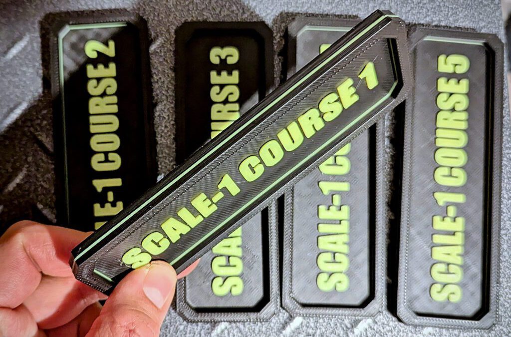
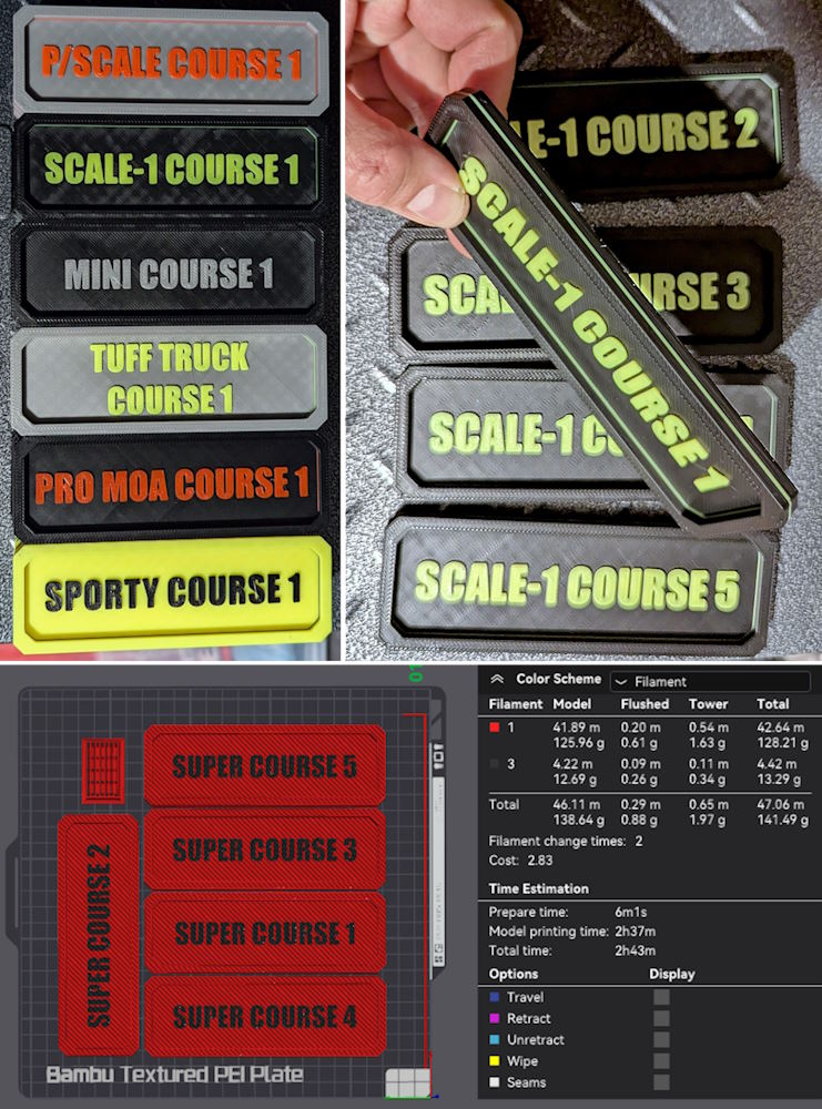
So, now we have these nifty course labels. Each one uses a bit under 30g of filament with 2 colors and probably less again with just one color.

PScale Print Preview

What’s Included

I’ve made a set of Course 1 to Course 5 for these classes:

  • Super
  • Pro/Moa
  • Sporty
  • Performance Scale
  • Mini
  • Scale-1 (experimental class)
  • Pricey’s Tuff Truck (experimental class)

I’ve also made a blank label, so you can print it in just one bright color and then write your class and course number on it in black marker. It’s up to you how you do it!

They’re 150mm x 50mm in size, and about 8mm deep. I didn’t want to go too thin nor too small, as they need to be visible and also heavy enough to not be blown away in windy conditions. This size feels good in the hand and it’s easy to read in the IMPACT font I used.

Materials Needed

You’ll need 25g to 30g of PLA+ filament per label, and of course, access to 3D printer.
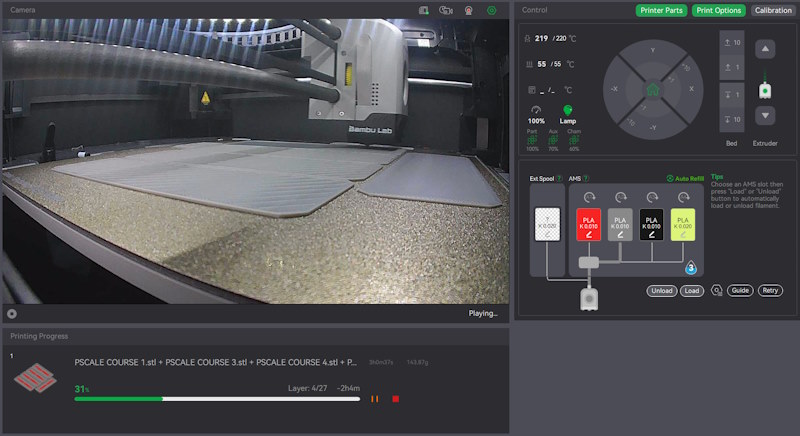
Comp Labels printing

How to Print

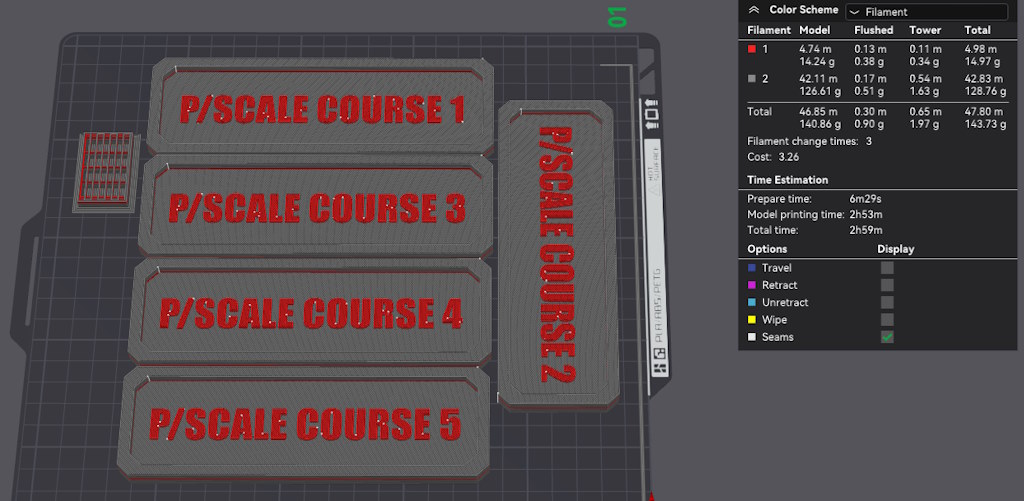
These are best printed at a draft resolution (0.24 on a 0.4mm nozzle or 0.3 or 0.36 on a 0.6mm nozzle). I used 2 walls (or shell thickness) and 10% Rectilinear infill.

Printing in two filament colors, care of Bambu AMS, at 0.3mm resolution, the total filament needed to print a set of 5 labels is 144g (or 48m of PLA+ filament).


Sporty Label Printing

Terms of Use

These files are provided for your personal use and enjoyment only. Please don’t print and sell them, nor the stl files (if you see them for sale in the wild, do me a solid and let me know!)

Please also don’t upload these to any of the online 3D printable sites. I’ve chosen not to do that and would appreciate you respecting that choice, as I’ve freely shared the files with you to print here on RC-TNT.com.

Thank you and please enjoy!

Craig Veness

Craig Veness

RC-TNT

Craig has been into radio control since the 90s and into RC crawling since about 2010, when a Losi MRC started the obsession! Now it's all rocks this and crawl that and upgrade all the things! ...You know how it is, right? Welcome home 🙂

My MN-82 Landcruiser Overhaul

My MN-82 Landcruiser Overhaul

Upgrades for the MN-82 Landcruiser

MN-82 Left Side

What This Is

Banggood sent me the MN-82 Landcruiser 79-Series Ute (or ‘pickup’ for you good Americans following along). It was attractive in stock form, but the suspension was way too firm and the vehicle was missing a certain something.

So, I got to work and this is what I came up with! Better looking, better performing and for minimial expense – especially if you already have a spare set of 1/24 wheels and tires to use with this pretty car!

MN-82 Landcruiser with Canopy

Terms of Use

These files are provided for your personal use and enjoyment only. Please don’t print and sell them, nor the stl files (if you see them for sale in the wild, do me a solid and let me know!)

Please also don’t upload these to any of the online 3D printable sites. I’ve chosen not to do that and would appreciate you respecting that choice, as I’ve freely shared the files with you to print here on RC-TNT.com.

Thank you and please enjoy!

What’s Included

  • Canopy for the drop bed;
  • Sliding door for the canopy;
  • Spacers to fit the rear springs to the front friction shocks;
  • 5mm to 8mm hex adapters to allow regular 1/24 wheels to fit;
  • Widened front and rear wheel arches to maintain scale tire coverage;
  • Anti-wrap bars for the rear leaf suspension, allowing you to remove all but the main leaf without sacrificing axle alignment;
  • Instructions on how to put it all together!


Materials Needed

  • MN-82 Landcruiser (buy here)
  • Injora (or other standard) 1/24 Wheels and Tires (links to the ones I’m using)
  • Jeweler’s (L) Philips Head Screwdriver
  • M2 Bolts and Screws
    • 16x 6mm x 1mm self-tapping screws for the canopy and fenders
    • 1x 20mm M2 bolt for the spare tire
    • 4x 20mm M2 bolts for the inner screws on the leaf spring brackets
    • 2x 20mm M2 bolts for the upper front shackle & anti-wrap bar fronts
  • Xacto blade or similar sharp cutting tool with strong handle
  • 1.6-1.8mm drill bit + drill
  • Conformal Coating for electronics use
  • Cotton wool bud for appling conformal coating
  • ~125g of PLA+ filament and access to 3D printer

Printable Parts List

  • Anti-Wrap Bar LHS.stl – print 1, PLA+ or PETG
  • Anti-Wrap Bar RHS.stl – print 1, PLA+ or PETG
  • Bed Canopy.stl – print 1, PLA+
  • Canopy Door.stl – print 1, PLA+
  • Front Fender LHS.stl – print 1, PLA+ or PETG
  • Front Fender RHS.stl – print 1, PLA+ or PETG
  • Front Shock Spacer 12.5mm (2) sliced.png – shows how I’d print it (ie. use brim)
  • Front Shock Spacer 12.5mm (2).stl – print 2, PLA+ or PETG
  • Hex Adapter LP (4).stl – print 4, PLA+ strongly recommended

How to Print

Print the bed canopy on its roof. Tree supports are needed, but that’s it.
Canopy door can just be printed flat.

Print the front and rear fenders on their upper, main arches.
Resist the urge to print the rear ones on the side that mates to the body.
Use tree supports. They’ll be fairly minimal but they’ll help.

Print the spacers and the hex adapters with a brim to assist with bed adhesion.

Model Preparation

  • Disconnect the battery.
  • Remove the four wheels.
  • Remove the 6 screws underneath that attach the body to the chassis.
    (Don’t stress if you get these wrong. Worst case, you unscrew the interior.)
  • When you remove the body, do it slowly! Prepare to unplug the battery & lights.
  • First: take a photo of the PCB before you unplug anything. Then unplug them.
  • Set the body aside. It should have headlights and power cable dangling.
  • Disconnect the motor and switch plugs. Disconnect the servo.
  • Remove the screw holding the PCB to the chassis plate. Remove the PCB.
  • Replace the PCB screw so you don’t lose it – it’s smaller than the others.

PCB Waterproofing

(Do this outside or somewhere with good ventilation, or wear a breathing apparatus.)

  • Place the PCB down on cardboard or kitchen paper towel.
  • Open the Conformal Coating bottle.
  • Dip cotton bud into the liquid, which will be like honey in consistency.
  • Dab it all over the single large chip on the plug side of the board.
  • Close bottle, dispose of bud, allow to dry for a couple hours.
  • Turn board over, open bottle, dip new bud into Conformal Coating.
  • Apply liberally all over the back side of the board except the holes.
  • Be careful not to miss any area – air holes can bite you later on when it gets wet!
  • Leave to set overnight. Once it’s firm to the touch and finished off-gassing, you’re good to go.
  • Re-install waterproofed board into chassis. Reconnect servo, motor and switch plugs.
Conformal Coating on PCB Back

Rear Shocks

  • Unscrew the rear shock tops and pop off the top half of the assembly.
    Remove the rear coil springs.
  • Press the shocks back together and screw back on.

Front Shocks

  • Unscrew the front shock tops and pop off the top half of the assembly.
  • Remove the front coil springs.
  • Drop the rear coils onto the lower halves.
  • Slide the spacers onto the upper halves.
  • Press back together and screw back on.

Leaf Springs

Examine the below picture for an idea of how it should look when done.

  • Pop off the rear shocks from the ball studs on the leaf spring brackets.
  • Unscrew your rear leaf springs.
  • Remove the plastic parts and just leave the metal mains.
  • Replace the original screws through the metal leaf spring.
  • Unscrew the inner screws on the leaf brackets (closer to chassis rails).
  • Place the anti-wrap arm under the inner of the two holes between the bracket and axle underside.
  • Screw in the M2 20mm screws to secure the top axle piece to the base, through the anti-wrap bar.
  • Remove the upper (closer to chassis) screws through the front leaf spring ‘sliding shackle’
  • Install M2 20mm screws through the shackle, with the spacer if it fits over your screw, then through the anti-wrap bars.
  • Press the rear shocks back onto the ball studs.
  • Test everything moves smoothly.

Canopy and Door

The canopy door should be installed before you screw the canopy to the bed.

Wiggle and push it into the rails at an angle from the inside. Some force is needed.
Work at it, you’ll get there. Once it’s in, it’s staying in. Slide back and forth a bit to loosen it up, as desired.

Align the canopy over the bed and do up your screws.

Attach the spare wheel.

Completed Model Rear-RHS

Rear Mud Guards

Hold the rear mud guards up to the side of the body and use a felt tip marker to mark where to drill.

Drill your holes (I used end and middle holes), then screw the mud guards on. Don’t over-tighten.

Front Mud Guards

Pop out the clips on the front fenders and then pop in the new ones.

The new ones should be popped in with the middle clip first, then the front, then the rear.

Attaching the Wheels

  • The adapters are necessarily a tight fit.
  • Press the adapters into the wheel hex nuts.
  • Use the rounded end of a screwdriver to get a nice, even downward force on them.
  • Take care to press them in as evenly as possible.
  • (If you mess up, don’t worry – these are a fast and easy part to print, and once they’re on, they’ll be reliable because of how tight the fit is).
  • Once in, carefully cut your plastic axle ends by 5mm and then fit the adapters and their attached wheels onto the shorter axles.
  • Attach the screw, and you’re done!

Finishing Up

Screw the body back onto the chassis, reconnecting the wires into the correct plugs.

(And by the way, there is a light kit for the MN-78 that you may be able to adapt to this thing, if you’re keen. Find that here.)

For any of the above, see the pictures here and my original video summary for help.

I hope this all goes smoothly! I’ve just done it following these instructions and it seems good.

Thanks and enjoy this one!
-Craig

Craig Veness

Craig Veness

RC-TNT

Craig has been into radio control since the 90s and into RC crawling since about 2010, when a Losi MRC started the obsession! Now it's all rocks this and crawl that and upgrade all the things! ...You know how it is, right? Welcome home 🙂

Total Rework for Redcat Ascent Fusion

Total Rework for Redcat Ascent Fusion

What This Is

This is my total rework for the Redcat Ascent Fusion.

When I tested the Redcat Ascent Fusion recently, it was capable, but also near its limit. I loved the premium finish and the aesthetic of the rig that Redcat has clearly set out to achieve (successfully, I might add).

However, the front end of the rig is very busy. Tuning is difficult. There’s bump steer under shock compression. The servo is limited by the janky angles in the CMS (Chassis Mounted Servo) setup. And there’s no rear tray or bed, which means in its stock config, the Ascent Fusion is not legal for WRCCA Performance Scale comps!

I wanted SOA (Servo On Axle) and I wanted a rear tray. To achieve that with this design, I needed to make FOUR changes:

  • SOA bracket and 4-link setup
  • Motor mount to accommodate this change without having to swap the motor for a stubby outrunner (this isn’t the Redcat Ascent Outrunner!)
  • Rear tray for WRCCA compliance
  • Cantilever shocks in order to fit the tray!
  • And I also threw in some extra value to address those wibbly-wobbly foams in the tires.

Finally, it’s all done! And it’s yours to download and print! Let’s go!

What’s It Cost?

Nothing! I’m giving this away. Print it yourself, build it, enjoy it.

All I ask in return is that you consider signing up to my email list (bottom of page). I won’t spam you. It’s basically a way for me to let you know when I release something cool that you’ll probably be interested in. If you like my YT channel and/or the files on these pages, it’ll probably be right up your alley.

Don’t worry, it’ll only be sporadic and I’ll safeguard your email address. I’m very pro privacy and will not abuse your trust. Thank you!

What You Get

You get twelve files in this download (as at v1.2):

  1. SOA v1.stl;
  2. Under-tray main spacer.stl;
  3. Spacers.stl;
  4. Tray.stl;
  5. Cam Inner.stl
  6. Cam Outer.stl
  7. 4-Link Motor Mount v1.stl
  8. Full Length Tray Bracket RHS 1.2.stl
  9. Full Length Tray Bracket LHS 1.2.stl
  10. 1.9 Verts for Ascent Fusion Fronts v2.stl
  11. 1.9 4.75 SoFines for Ascent Fusion Rears v3.stl
  12. READ ME.txt


Changelog:

1.1: added missing cam pieces.

1.2: modified Tray so rear-middle hole aligns with main center spacer.

How To Use

Start with the READ ME.txt file in the zip file. That tells you about these files, how to print them, and what hardware you also need for the conversion.

Pay particular attention to the print guide for the servo mount (SOA v1.stl) as the orientation of this part on your print bed will affect its strength.

Alternatively, you can buy this part in stainless steel from Shapeways (here – you’ll need to tap your own threads, be warned) and print everything else. (Update: there’s a better product already on the market, thanks to youtube commenter @Offroadflicks. Check out the Boco mount, it’s quite a bit cheaper at USD$34 (at that price, it’s the best option, I think! Also, https://1tenth.com has a mount for regular Ascent from axle; they’re working on one for the Fusion axle as of mid July 2024. Watch their site/socials for updates)

Also suggest you check out the video at the top of this page for some context. You’ll be able to see the rig moving, and to get an idea of what you’re aiming to build.

It should all ‘just work’ but let me know if you hit a snag. Happy tinkering!

Reworked Ascent Fusion Rear-Left
p

Terms of Use

These files are provided for your personal use and enjoyment only. Please don’t print and sell them, nor the stl files (if you see them for sale in the wild, do me a solid and let me know!)

Please also don’t upload these to any of the online 3D printable sites. I’ve chosen not to do that and would appreciate you respecting that choice, as I’ve freely shared the files with you to print here on RC-TNT.com.

Thank you and please enjoy!

Scale-1 Conversion for SCX10 III JLU

Scale-1 Conversion for SCX10 III JLU

2024 ECCF Scale-1 1st Place

What This Is

The files I developed to transform my Axial SCX10 III JLU into a WRCCA Scale-1 competition beast!

These parts aren’t perfect and you’ll need a little imagination (and scissors!) to meld the body with this tray. You’ll also want to drill (6mm) out the roof rack holes and use the shortest of the cups included in the file list underneath to get the length right.

I used flat M3 screws for the most part, 8mm and 12mm, as well as 8 or so 8mm M3 countersunk screws.

These parts aren’t perfect, but they’ll get you pretty close to the end result here.

What’s It Cost?

Nothing! I’m giving this away. Print it yourself, build it, enjoy it.

All I ask in return is that you consider signing up to my email list (bottom of page). I won’t spam you. It’s basically a way for me to let you know when I release something cool that you’ll probably be interested in. If you like my YT channel and/or the files on these pages, it’ll probably be right up your alley.

Don’t worry, it’ll only be sporadic and I’ll safeguard your email address. I’m very pro privacy and will not abuse your trust. Thank you!

original scx10 iii jlu front rear

What You Get

You get 15 files in this downloadable zip file:

  1. Bed.stl – the main tray
  2. LHS Connector.stl – goes left of tray
  3. LHS Door Clip.stl – goes outside front panel
  4. LHS Flare.stl – print in TPU
  5. LHS Front Panel.stl – goes at front
  6. LHS Rear Panel.stl – connects to LHS Connector
  7. Rear Connector.stl – bolts to rear of tray
  8. Rear Panel.stl – bolts to Rear Connector and Rear Panels
  9. RHS Connector.stl – goes right of tray
  10. RHS Door Clip.stl – goes outside front panel
  11. RHS Flare.stl – print in TPU
  12. RHS Front Panel.stl – goes at front
  13. RHS Rear Panel.stl – connects to RHS Connector
  14. Roof Rack Cups.stl – use to adjust roof rack under tray
  15. Read Me.txt
Preview of parts

How To Use

Here’s how to print them:

Quantity: 1 of each piece.

Material: print all* in PETG or PLA+ (any brand) – I’ve had success with eSUN and SUNLU. There’s no standard for PLA+, but it gives strength and flexibility to PLA and has been good.

*Except for LHS and RHS Flare – suggest these be done in TPU (any). They’ll still be okay in PLA+ but TPU will help ensure longevity on the rocks!

Resolution: I’ve been using 0.24, but any of 0.2, 0.24 or even 0.28 will work. Lower res is stronger, higher res is smoother. 0.24 is a good mid-point.

Infill: doesn’t really matter, but 15% should be fine.

Walls: 3, gives a little extra strength on those thinner parts.

Supports: none, except for the RHS and LHS Front Panels, where it needs just a smidge under those connecting parts.

Rafts: none

Orientation: on the flat side of all parts. They’re designed to just work. Align the flares on the inside part that connects to the side panels. Cups just stand up.

work in progress

Assembly

Screws. You’re gonna need em! I used flat M3 screws in 8mm and 12mm, and also countersunk M3 screws in 8mm. Worked nicely.

You’ll also need two M2.5 screws in 12 to 16mm for securing the bottom of the LHS and RHS Rear Panels to the Rear Panel. Do these up first before you screw in that last LHS/RHS Flare screw.

I used a little tape behind the LHS/RHS Rear Panel and LHS/RHS Front Panel pieces to help line them up with the lexan interior. I also poked a few holes in that interior so the screws would go though and help align it.

Lastly, the front hole of the LHS/RHS Front Panel goes under the rearmost screw of the front wheel wells on the body. That’ll also help align it.

Don’t over-tighten things. You’ll probably find PLA+ more tolerant of enthusiastic screw tightening than PETG, but take it easy and use hand tools rather than a drill. Once assembled, she’s a pretty rugged thing.

Enjoy!

Scale-1 Conversion for SCX10 III JLU
p

Terms of Use

These files are provided for your personal use and enjoyment only. Please don’t print and sell them, nor the stl files (if you see them for sale in the wild, do me a solid and let me know!)

Please also don’t upload these to any of the online 3D printable sites. I’ve chosen not to do that and would appreciate you respecting that choice, as I’ve freely shared the files with you to print here on RC-TNT.com.

Thank you and please enjoy!

Window Webbing for Tamiya Hornet

Window Webbing for Tamiya Hornet

Window Webbing for Tamiya Hornet

What This Is

Custom designed window webbing to fit your Tamiya Hornet!

You’ll need to secure it inside the body and though it’ll work with clear windows, I’ve designed these to fit with the windows removed entirely.

Use double-sided tape, hot glue or even a 3D print pen to draw these into place.

What’s It Cost?

Nothing! I’m giving this away. Print it yourself, build it, enjoy it.

All I ask in return is that you consider signing up to my email list (bottom of page). I won’t spam you. It’s basically a way for me to let you know when I release something cool that you’ll probably be interested in. If you like my YT channel and/or the files on these pages, it’ll probably be right up your alley.

Don’t worry, it’ll only be sporadic and I’ll safeguard your email address. I’m very pro privacy and will not abuse your trust. Thank you!

What You Get

You get two files in this download:

  1. LHS webbing piece;
  2. RHS webbing piece.
Window Webbing Pieces for Tamiya Hornet

How To Use

Here’s how to print them:

Quantity: 1 of each piece.

Material: PETG or PLA+ (any brand) – we’ve had success with eSUN and SUNLU. There’s no standard for PLA+, but it gives strength and flexibility to PLA and has been good.

Resolution: I’ve been using 0.24, but any of 0.2, 0.24 or even 0.28 will work. Lower res is stronger, higher res is smoother. 0.24 is a good mid-point.

Infill: doesn’t really matter, but 15% should be fine.

Walls: 4 or 6, gives a little extra strength on those thinner parts.

Supports: none

Rafts: none

Orientation: on the flat side of both parts. They’re designed to just work.

Assembly

I used a 3D printer pen to ‘draw’ mine into the cockpit. You could just use double-sided tape, ShoeGoo or hot glue. Whatever works.

Enjoy!

Window Webbing installed in Tamiya Hornet
p

Terms of Use

These files are provided for your personal use and enjoyment only. Please don’t print and sell them, nor the stl files (if you see them for sale in the wild, do me a solid and let me know!)

Please also don’t upload these to any of the online 3D printable sites. I’ve chosen not to do that and would appreciate you respecting that choice, as I’ve freely shared the files with you to print here on RC-TNT.com.

Thank you and please enjoy!