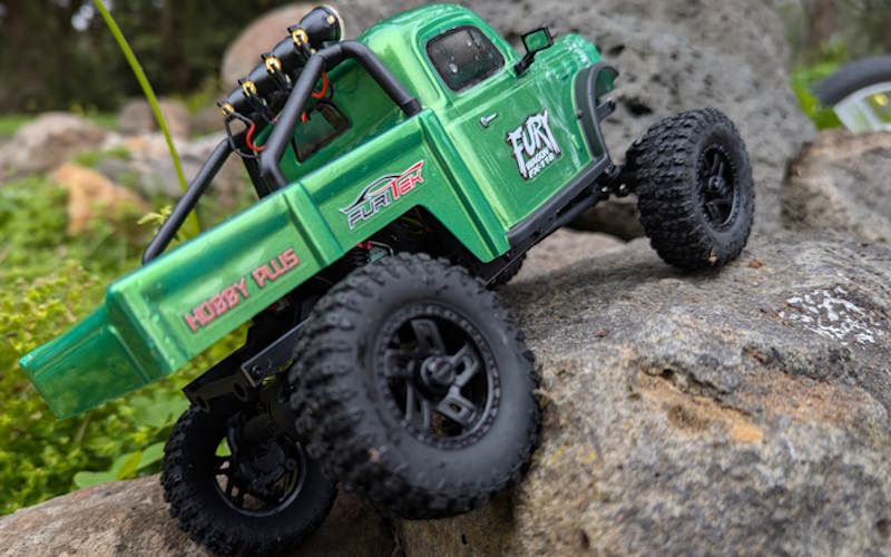
Cross Brace for 560 Motor in FMS FCX10
Long Motor Cross Brace for FMS FCX10
What This Is
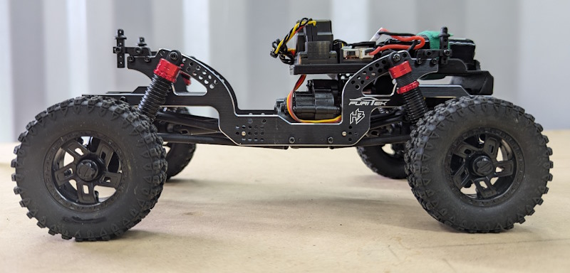
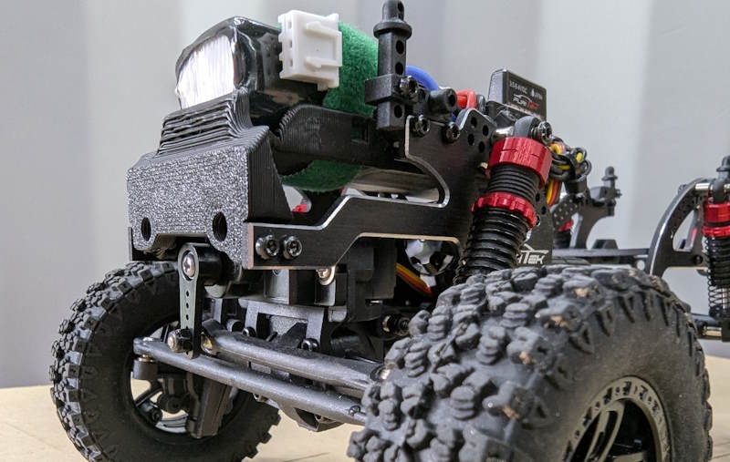
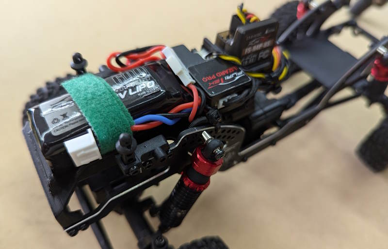
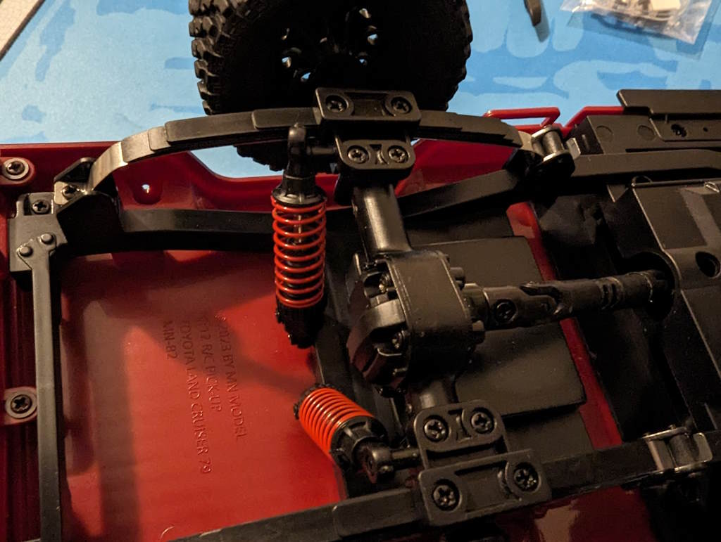
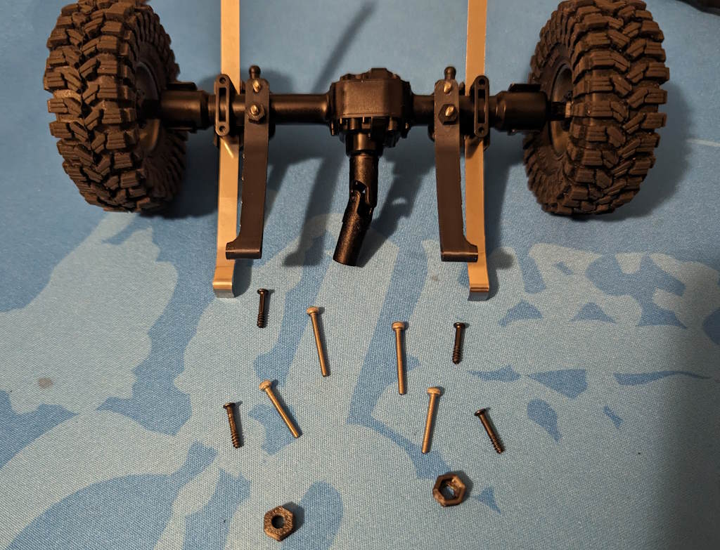
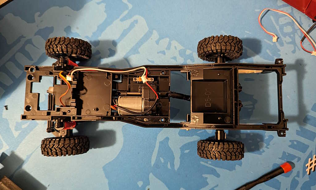
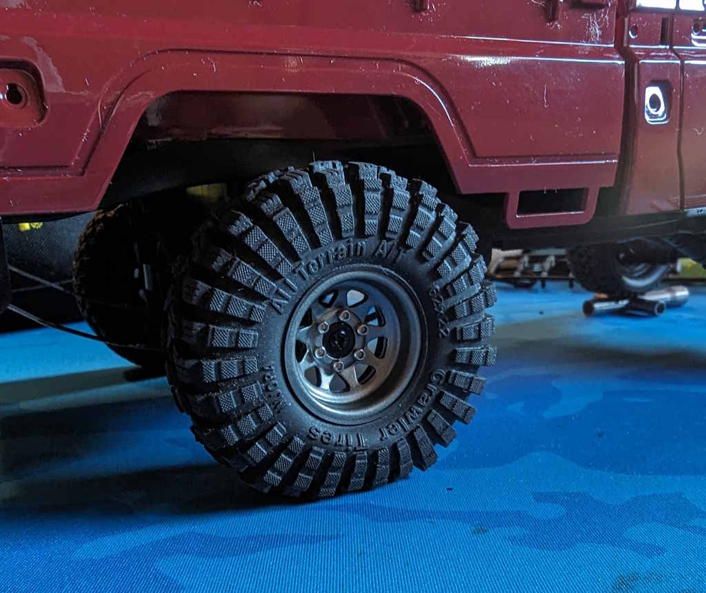
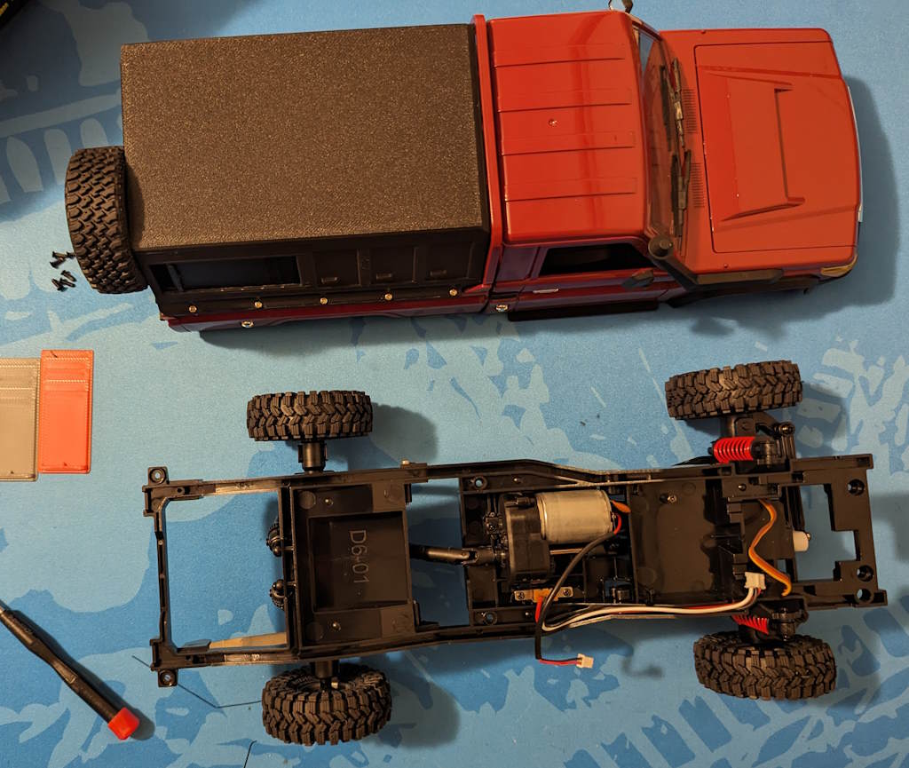
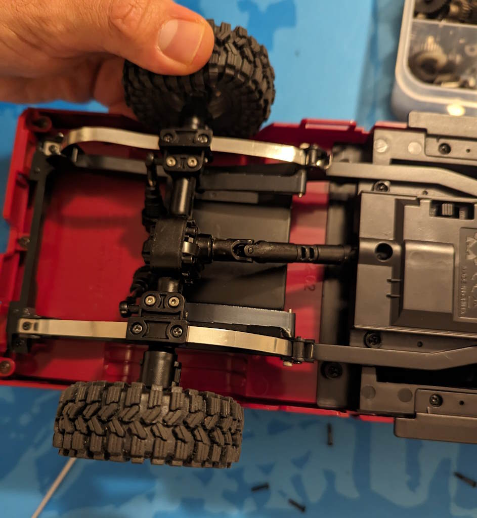
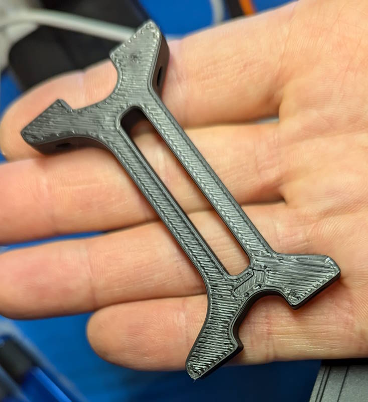
This is a one-piece cross-brace that’s designed to replace the stock piece in the FMS FCX10 K5 Blazer. It sits between the motor and the servo and provides chassis rigidity and receiver holes for the shock hoop screws.
Print this tray and install it using the hardware that came with the car. You’ll have more room for your longer motor with no loss in rigidity or strength. Win-win!

What’s Included
The zip file below contains:
- RC-TNT Cross Brace for FMS FCX10.stl
- Read Me.txt
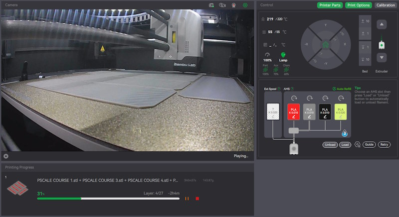
How to Print
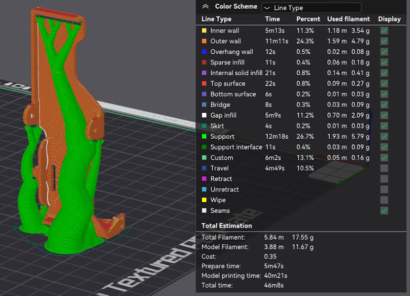
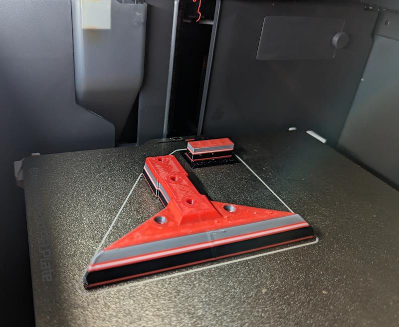
I printed in PLA+, though PLA, PETG and other rigid filaments should be fine. I’d suggest these settings:
– 0.4mm nozzle (or bigger)
– 0.24mm layer size (I used 0.3mm with my 0.6mm nozzle)
– 4 to 6 wall width (or wall or shell layers)
– 60% infill, cubic (25% minimum)
– No supports, brim or other helpers. Just print it flat and you’re done.
Installation
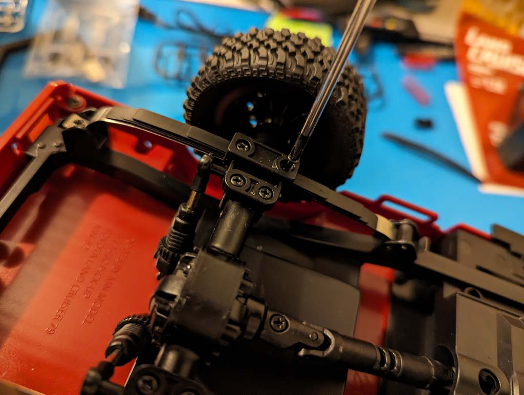
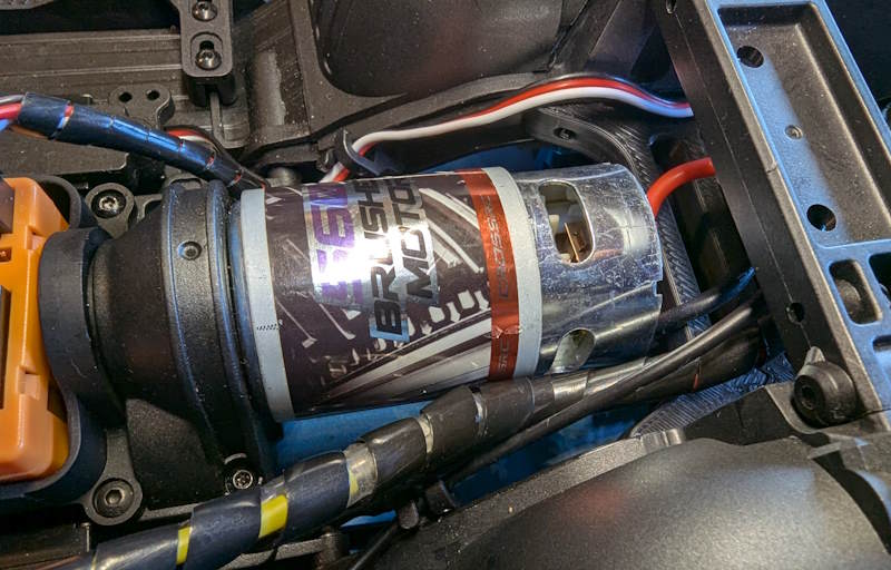
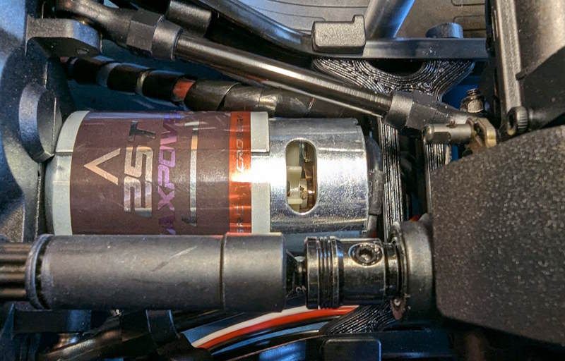
Simply remove the stock cross-brace that sits between the motor and the servo in your FMS FCX10. Install this one, with the deeper gap at the back. There’s a small arrow on the top surface that points to the front of the chassis.
Now you have 6mm more room for a 560 sized motor, or for whatever other crazy thing you’re trying to run in the car.
Terms of Use
These files are provided for your personal use and enjoyment only. Please don’t print and sell them, nor the stl files (if you see them for sale in the wild, do me a solid and let me know!)
Please also don’t upload these to any of the online 3D printable sites. I’ve chosen not to do that and would appreciate you respecting that choice, as I’ve freely shared the files with you to print here on RC-TNT.com.
Thank you and please enjoy!

Craig Veness
RC-TNT
Craig has been into radio control since the 90s and into RC crawling since about 2010, when a Losi MRC started the obsession! Now it's all rocks this and crawl that and upgrade all the things! ...You know how it is, right? Welcome home 🙂